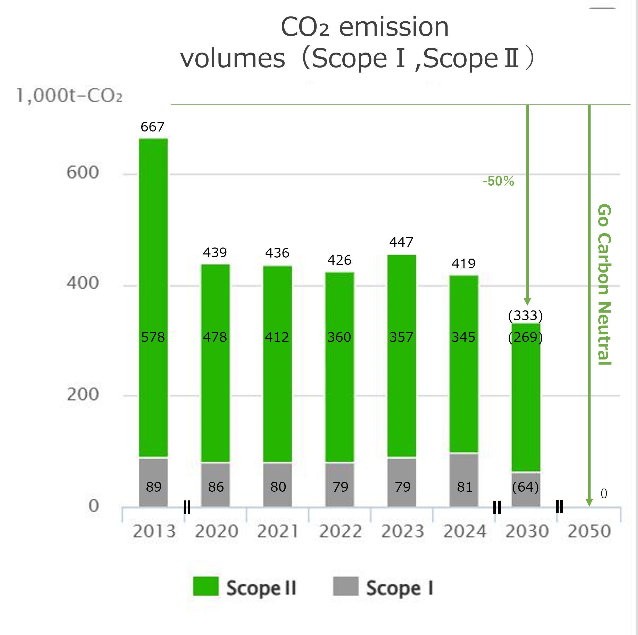
The Group is aiming to achieve carbon neutrality by 2050.
The Group aims to achieve carbon neutrality by 2050 through the "CO2 Emissions Reduction Plan" roadmap below.

Envisage virtually zero greenhouse gas emissions by 2050, the Group has createdits own target to reduce CO2 emissions by 50% by FY2031, compared with FY2014 emissions at all domestic production bases. Firm measures to achieve this reduction have been incorporated.
The closure in March 2016 of the Hirakata Division’s Osaka Shop, which used to manufacture and sell billets, has reduced CO2 emissions and increased energy intensity. The Group has been introducing energy saving technologies such as regenerative burners, which achieve both energy savings and low NOx emissions, and a “direct rolling process”, which obviates the need for a reheating process for billets. The Group will seek to implement further energy saving activities. We will also reduce CO2 emissions by replacing fuels with a high CO2 emission factor, such as heavy oil and kerosene, which are currently used for some of our operations, with fuels with a low environmental impact such as city gas and LNG. We will also proceed with other eco-friendly activities such as use of in-house photovoltaic power generation, and tree planting. In considering the configuration of Scope Ⅰ and Scope Ⅱ of our CO2 emissions, we should not ignore the CO2 emission factor from electricity. The Group’s carbon neutral activities will use 0.37 kg of CO2 per kWh (FY2031) as the CO2 emission factor from electricity, in accordance with the Federation of Electric Power Companies of Japan’s “Action Plan for Achieving a Low Carbon Society in the Electric Power Industry (2015).”
|
Category |
ScopeⅢ (1,000 t-CO2) |
||
|
FY2024 |
FY2025 |
Proportion (%) |
|
|
1. Products and services purchased |
90.466 |
91.483 |
29.9 |
|
2. Capital goods |
18.517 |
4.934 |
1.6 |
|
3. Fuel and energy-related activities not included in Scope I or II |
70.726 |
138.643 |
45.2 |
|
4. Upstream logistics |
29.661 |
32.990 |
10.8 |
|
5. Waste generated by operations |
5.375 |
4.194 |
1.4 |
|
6. Business travel |
0.128 |
0.129 |
0.0 |
|
7. Employee commuting |
0.420 |
0.421 |
0.1 |
|
8. Upstream leased assets |
- |
- |
- |
|
9. Downstream logistics |
16.920 |
16.743 |
5.5 |
|
10. Processing of products for sale |
5.078 |
3.827 |
1.2 |
|
11. Use of products sold |
- |
- |
- |
|
12. Disposal of products sold |
14.238 |
13.059 |
4.3 |
|
13. Downstream leased assets |
- |
- |
- |
|
14. Franchising |
- |
- |
- |
|
15. Investment |
- |
- |
- |
|
Total |
251.529 |
306.423 |
100 |
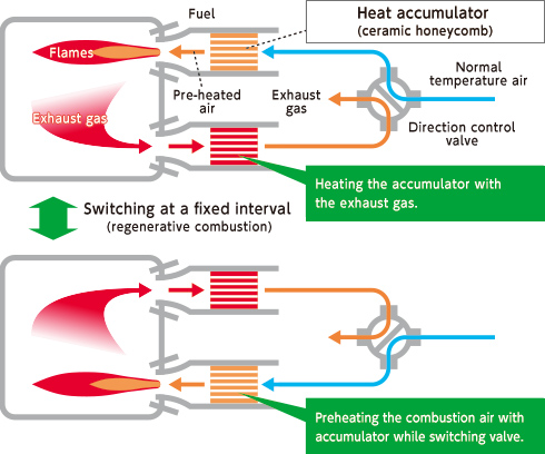
When a reheating furnace for steel is used, the internal temperature of the furnace reaches as high as 1,200°C.
To maintain this temperature, it is necessary to continuously feed fresh air and fuel into the furnace and keep the furnace burning.
Therefore, improving the efficiency of energy use has become a major challenge in reducing environmental impact.
To address this challenge, we have gradually introduced regenerative burners, which are energy-saving burners.
A regenerative burner system is composed of two burners, each of which is integrated with a heat accumulator. When one burner is firing, exhaust gas passes through the accumulator of the other burner to heat the accumulator, thus recovering energy from the exhaust gas.
When the other burner burns, combustion air is preheated by allowing it to pass through the heat accumulator that was previously heated. In this way, the energy of exhaust gas, which is conventionally discarded, can be recovered, achieving high combustion efficiency.
This heat storage effect improves heat exchange efficiency, resulting in energy saving.
Also, to perform low NOx (nitrogen oxide) combustion, fuel and air are directly sprayed into the high temperature furnace from separate nozzles, which significantly slows down the combustion speed and substantially reduces NOx generation.
■ Structure of regenerative burners
We continually pursue energy and resource saving in production processes while ensuring a high level of product quality.
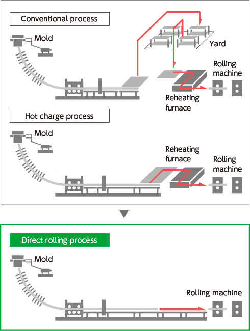
As an initiative to this end, we introduced an innovative production process called “direct rolling,” which directly connects the casting process and the rolling process.
Conventionally, steel scrap is melted in an electric arc furnace and then cooled and solidified by being passed through a continuous casting machine to form semi-finished products called “billets.”
After that, the cooled billets are reheated to a predetermined temperature in a reheating furnace, to be processed into the intended form and size. This is the conventional process.
In recent years, the hot charge rolling process, whereby the billets are charged into a reheating furnace at a higher temperature and rolled, has been widely employed.
At Kyoei Steel, in order to work on further energy saving in the rolling process, we have introduced direct rolling technology, which enables direct rolling after casting.
As a result, reheating has become unnecessary and the amount of fuel use has been substantially reduced.
Also with lower CO2 emissions, we have achieved a production process that is environmentally friendly and has little environmental impact.
■ Schematic diagram of processes (conventional → direct rolling)